มีสินค้าพร้อมส่ง สินค้าขายดี
AXL F DOR4/2 AC/220DC 1F
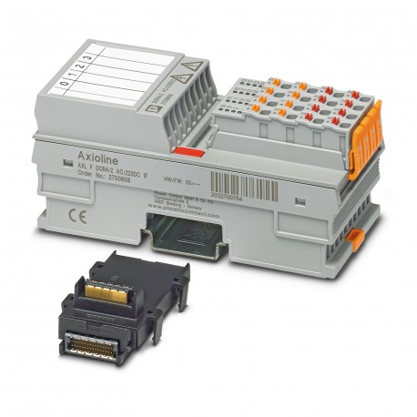
AXL F DOR4/2 AC/220DC 1F 2700608 PHOENIX CONTACT I/O module
$0.00
ดอลลาร์สหรัฐ
มีสินค้าในสต็อก
ข้อมูลจำเพาะหลัก
:
For DC see load limit curve, e.g., the following values:
พิมพ์:
block modular
ความลึก:
54 mm
ความกว้าง:
53.6 mm
ข้อมูลผู้จำหน่าย
ผลิตภัณฑ์: 0
โดยปกติจะจัดส่งภายใน 2-3 วันทำการ
รับประกันคุณภาพ
จัดส่งรวดเร็ว
ฝ่ายสนับสนุนด้านเทคนิค
ข้อกำหนดทางเทคนิค
| พารามิเตอร์ | ค่า |
|---|---|
| For DC see load limit curve, e.g., the following values: | |
| พิมพ์ | block modular |
| ความลึก | 54 mm |
| ความกว้าง | 53.6 mm |
| ความสูง | 126.1 mm |
| กระแสไฟฟ้าที่ดึงมา | max. 280 mA (all relays pick up) |
| ประเภทผลิตภัณฑ์ | I/O component |
| ประเภทการติดตั้ง | DIN rail mounting |
| กลุ่มผลิตภัณฑ์ | Axioline F |
| แรงดันไฟฟ้าที่จ่าย | 5 V DC (via bus base module) |
| ชื่อการเชื่อมต่อ | Axioline F connector |
| การแก้ไขบทความ | 02 |
| ระดับมลพิษ | 2 |
| ความยาวในการลอก | 8 mm |
| วิธีการเชื่อมต่อ | Bus base module |
| ตำแหน่งการติดตั้ง | any (observe temperature and current derating) |
| จำนวนเอาต์พุต | 4 (floating) |
| ขอบเขตการส่งมอบ | including bus base module and Axioline F connectors |
| กระแสสวิตช์ชิ่ง | max. 8 A AC (cos phi = 1) |
| พื้นที่ป้อนที่อยู่ | 0 Byte |
| หมายเหตุเกี่ยวกับขนาด | The depth applies when a TH 35-7.5 DIN rail is used (in accordance with EN 60715). |
| ความสามารถในการสลับ | max. 2000 VA |
| ความเร็วในการส่งกำลัง | 100 Mbps |
| ภาพวาดแสดงขนาด | |
| หมายเหตุเกี่ยวกับใบสมัคร | Only for industrial use |
| พื้นที่ที่อยู่เอาต์พุต | 1 Byte |
| ความถี่ในการสลับ | max. 6 (per minute) |
| ระดับการป้องกัน | IP20 |
| จำนวนอินเทอร์เฟซ | 2 |
| หมวดหมู่แรงดันไฟเกิน | III (EN 61010-2-201/UL 61010-2-201), up to 2000 m above sea levelII (EN 61010-2-201/UL 61010-2-201), up to 3000 m above sea level |
| การกำหนดมาตรฐาน | Ambient conditions |
| เทคโนโลยีการเชื่อมต่อ | 2-conductor |
| ประเภทการสลับหน้าสัมผัส | N/O contact |
| อายุการใช้งานเชิงกล | 10x 106cycles |
| ข้อมูลพารามิเตอร์ที่จำเป็น | 1 Byte |
| แรงดันอากาศ (การทำงาน) | 70 kPa ... 106 kPa (up to 3000 m above sea level) |
| มาตรฐาน/ข้อกำหนด | IEC 61850-3 |
| หน้าตัดตัวนำ AWG | 24 ... 16 |
| ข้อมูลการกำหนดค่าที่จำเป็น | 6 Byte |
| หน้าตัดตัวนำแข็ง | 0.2 mm² ... 1.5 mm² |
| หมายเหตุเกี่ยวกับวิธีการเชื่อมต่อ | Please observe the information provided on conductor cross sections in the “Axioline F: system and installation” user manual.When selecting the cables, please note that in the case of a small conductor cross section and high current, the terminal point temperature may be up to 30 K above the ambient temperature. |
| หน้าตัดตัวนำแบบแข็ง | 0.2 mm² ... 1.5 mm² |
| อุณหภูมิแวดล้อม (ขณะใช้งาน) | -25 °C ... 60 °C (max. 6 A/channel for wall mounting on horizontal DIN rail; max. 4 A/channel for any mounting position) |
| ความดันอากาศ (สำหรับการจัดเก็บ/ขนส่ง) | 70 kPa ... 106 kPa (up to 3000 m above sea level) |
| หน้าตัดตัวนำมีความยืดหยุ่น | 0.2 mm² ... 1.5 mm² |
| ความชื้นที่อนุญาต (ในการใช้งาน) | 5 % ... 95 % (non-condensing) |
| หน้าตัดตัวนำแบบยืดหยุ่น | 0.2 mm² ... 1.5 mm² |
| แรงดันไฟฟ้าทดสอบ: หน้าสัมผัสรีเลย์ / ตรรกะ | 4 kV |
| อุณหภูมิแวดล้อม (การจัดเก็บ/การขนส่ง) | -40 °C ... 85 °C |
| ความชื้นที่อนุญาต (ระหว่างการจัดเก็บ/ขนส่ง) | 5 % ... 95 % (non-condensing) |
| กำลังไฟฟ้าสูงสุดที่กระจายได้ในสภาวะปกติ | 1.4 W |
| แรงดันไฟฟ้าทดสอบ: หน้าสัมผัสรีเลย์ / กราวด์ใช้งาน | 4 kV |
| ความสามารถในการสลับตามมาตรฐาน IEC 60947-5-1 | 6 A (120 V (AC15)) |
| แรงดันไฟฟ้าทดสอบ: หน้าสัมผัสรีเลย์/หน้าสัมผัสรีเลย์ (หน้าสัมผัสเปิด) | 1 kV, 50 Hz, 1 min. |
| แรงดันไฟฟ้าทดสอบ: หน้าสัมผัสรีเลย์/หน้าสัมผัสรีเลย์ (ขั้วต่อตัวผู้ที่อยู่ติดกัน) | 2.5 kV |
คำอธิบายผลิตภัณฑ์
AxiolineF, Relay module, Relay outputs:4 (potential-free), Open contact, 220 VDC, 230 VAC, local bus transmission rate:100 MBit/s, protection index: IP20, including bus socket module and AxiolineF con
คุณสมบัติหลัก
- คุณภาพระดับอุตสาหกรรม
- เป็นไปตามมาตรฐาน RoHS
- ได้รับการรับรอง CE
- รับประกัน 1 ปี
เอกสารผลิตภัณฑ์
เอกสารข้อมูลทางเทคนิค
ข้อมูลจำเพาะทางเทคนิคและข้อมูลประสิทธิภาพ
คู่มือผู้ใช้
คู่มือการติดตั้งและการใช้งาน


